| |
|
Introduction |
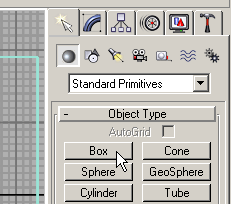
Day Two: ModelingAt the beginning of the second part of the tutorial you have three main geometric objects, cover of the table, four simple materials applied to them and two sources of light - Omni and Target Spot. Our next step will be modeling of the frame of the table and its legs. Construct box with length of 210, width of 90 and height of 10 cm.
Fig 01. Create Tab
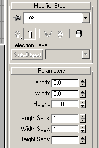
Fig 02. Frame of the Table It's frame that makes table construction rigid. Create another box with 80 cm height and cross-section of 5x5 cm and place it at the corner of the table.
Fig 03. Leg of the Table
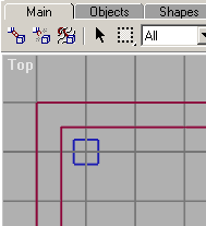
Fig 04. Leg of the Table: Top View
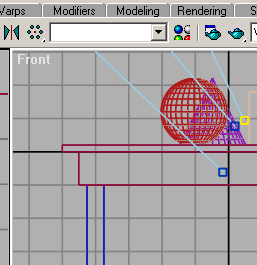
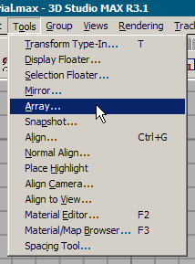
Fig 05. Leg of the Table: Front View Table has four legs, but we do not need to create all of them one by one. There is array function that can make all of the legs we need. Select existing leg and choose Tools/Array.
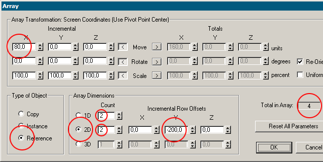
Fig 06. Tools/Array Arrays in MAX are somewhat tricky, so experiment with them to fully understand how they work. Increment 80 means that distance between every object copied in X direction will be 80. Checked Reference radio-button in Type of Object window means that additional legs will be not full copies of the leg, but references from the original. Any changes made to original leg will propagate to its references. So if you change the cross section of the original, references will change the same way. Increment -200 means that distance between every object copied in Y direction will be 200.
Fig 07. Array
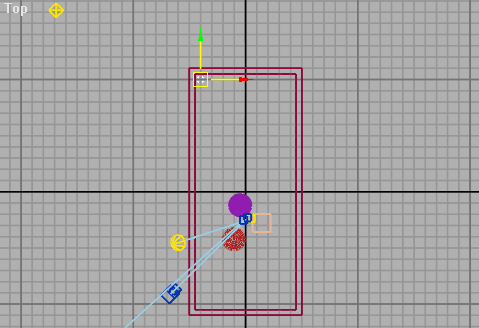
Fig 08. One Leg
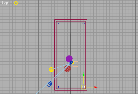
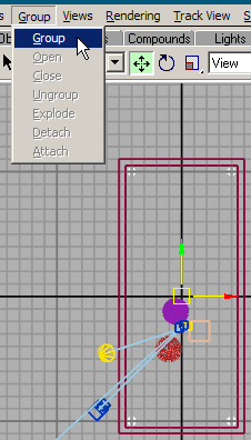
Fig 09. Array of Legs Press SHIFT key and select all four legs and group them. Now you can work with group as with one object.
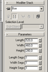
Fig 10. Group/Group Groups are the tool to organize objects in your scenes. With hundreds objects in the scene it became pretty messy. Now create box that represents our room, length 520, width of 460 and height 280 cm.
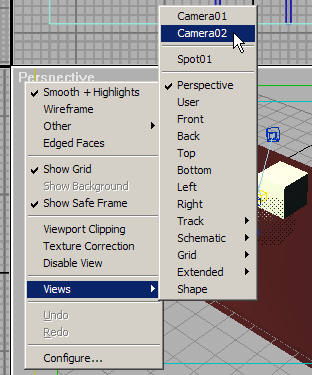
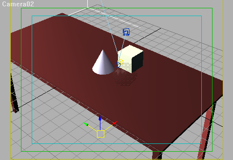
Fig 11. Room Objects in MAX consist of faces (triangles). Face has two sides, but normally only one is visible. When you look at the box from outside you see the box, because normals are looking in your direction. Move camera inside the box and look from this point of view.
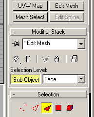
Fig 12. Select Camera It will look like there is no box exists at all. You need to flip normals, to make box faces to look inward. Apply Edit Mesh modifier, press Sub-Object button to make you able to work with individual faces.
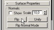
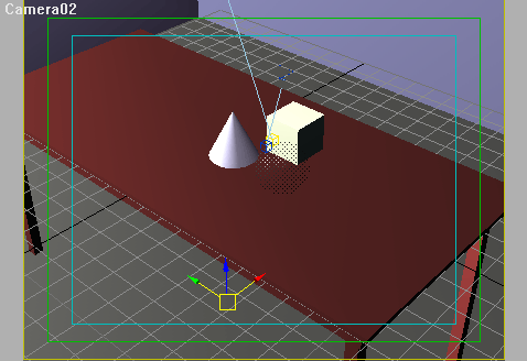
Fig 13. Edit Mesh/Sub-Object Select all the faces of the box with CTRL-A, press Flip button.
Fig 14. Flip Normals Now box is visible from the camera viewpoint. To play more with normals and to better understand them download example file.
Fig 15. Before
Fig 16. After |
|
| |